For pilots using Xplane for maintaining proficiency or for flight training, it is important to have a cockpit layout similar to their real airplane. Unfortunately, Xplane does not make this process simple. Creating the same look and feel of your own airplane requires building new instruments and applying custom textures. Documentation on how to do this is sparse, and in many cases they simply don’t exist. It took me quite a while to figure this out. I had to get into the nuts and bolts of how Xplane runs. In this post I will attempt to summarize my experiences in the hope that it can alleviate some frustration for those in a similar situation.
Software
For 3D modeling I use Blender (version 2.82 at the time of this writing), and for editing 2D images I use Gimp (version 2.10). Of course there are other options, such as AC3D and Photoshop, but Blender and Gimp are free. These are powerful tools to have in your back pocket anyway. A forewarning, though: they are not easy to learn. I strongly recommend you follow one of the many comprehensive tutorials available for Blender and Gimp. Trying to figure out Xplane without a good knowledge of Blender is guaranteed to be a frustrating experience.
Xplane’s file structure
The nice thing about Xplane is that all of the aircraft-related files are in plain text format. They can be opened with an editor like notepad or vim. The root file of each airplane has the extension .acf. This file contains all of the aerodynamic definitions as well as the names of the 3D objects that make up the visuals. One important thing to realize is that the flight model and the visual model are completely decoupled from each other. The 3D objects are for visual effects only, and have no impact on the flying characteristics. In other words, you can make the airplane look like an elephant, and still make it fly like a glider.
Even though .acf is a text file, it is meant to be opened only with Xplane’s Plane Maker. When you open this file in Plane Maker, you will be presented with an external view of the airplane. You can go into the Object menu on the left panel and check all of the various objects that make up the airplane’s visual models. To see the cockpit panel, you will have to uncheck the fuselage, seats and other objects that are in the way, and zoom up real close (use “=” for zooming in).
The flight model is in separate menus on Plane Maker. This is where you can set engine and propeller information, wing dimensions, fuselage cross sections and a whole lot of information that determine the flying characteristics. Changing these parameters will have no effect on the visual representation. Modifying the flight parameters is a different topic, so I won’t discuss it here.
The acf file references a bunch of other files, but the 3D objects are the ones I will discuss here. These files are under the directory objects/. There will be sub-directories as well, and each panel instrument is likely to be in its own directory. Each 3D object has an extension .obj. Examples of 3D objects include altimeter, radios, GPS, yoke, etc..
Xplane2Blender
This is a plugin for Blender that allows one to export from Blender to Xplane’s obj format. Here is a snapshot of my plugin panel in Blender.
Unfortunately, despite what its name might suggest, this plugin does not import Xplane’s objects into Blender. It is strictly a Blender-to-Xplane exporter only. If you are looking to modify an existing airplane in Xplane, this is where you will hit the first major obstacle.
However, not all is lost. If you google obj file format, the first one that come up is the wavefront obj. Wavefront is also a 3D file format, and it is surprisingly similar to Xplane’s obj file structure. It is relatively easy to write a script to convert Xplane’s obj into wavefront obj, and then read it into Blender. However, all of the Xplane animations and commands will be lost during this translation.
There are other 3D programs like AC3D and Sketchup that have import modules for Xplane objects. As far as I know, none of them will preserve the animations and manipulations. In my case, I decided it is best to start by learning Xplane’s obj file format and write my own conversion code.
Xplane’s obj file format
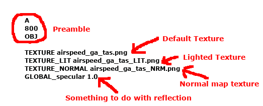
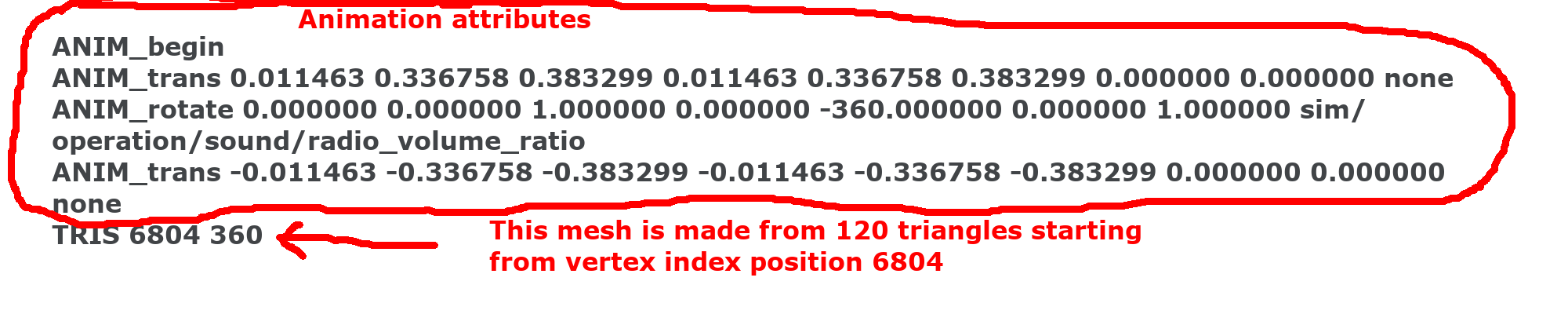
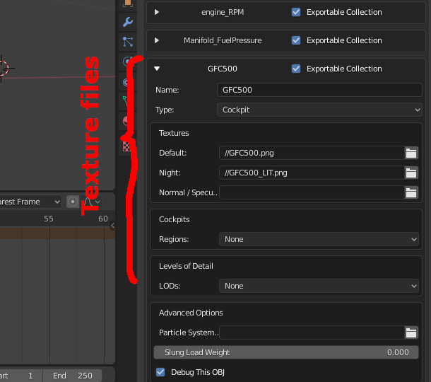
As mentioned earlier, this is a plain text file. The first block contains the name of the texture files used to wrap the object. If you don’t know what a texture file is, you should review the concept elsewhere. It is widely used in Blender as well as in any 3D modeling software. Texture files are typically in PNG or DDS format. Three texture files are used in Xplane: a default texture, a lighted texture (parts that glow in the dark) and a normal map texture. The default texture is sufficient for now. I’ll say more about the others later.
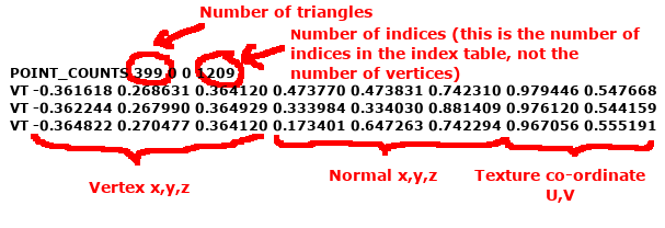
The next block is a large table of vertices. Each line is a vertex, and begins with the prefix “VT”. It contains the x,y,z coordinates of the vertex , its vertex normal (which is also x,y,z) and the u,v texture coordinates for that vertex. So there are a total of 8 numbers for each vertex.
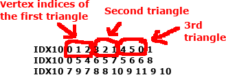
The next block references the vertices that form the individual triangles of a mesh structure. Each line begins with a prefix “IDX”. This is basically the position of each vertex in the previous vertex table. So “0” refers to the first item in the vertex table, “1” refers to the second item and so on. For brevity, these are arranged in blocks of 10, using the prefix “IDX10”. In the example below, the first triangle is created by the 0th, 1st and 2nd vertices in the vertex table.
The next block is where the mesh structure is created. The prefix is “TRIS”, and it has the starting IDX number and the number of vertices that form that mesh. Since a mesh is created from triangles, the number of vertices here must be a multiple of 3. Prior to the TRIS command, a number of Xplane-specific attributes are specified for that mesh. Manipulators specify an action, such as a push button, a throttle lever, or flip switch, etc.. They will also include the Xplane’s internal variables connected to that manipulation. Animation specify how the part moves in response to an internal variable of Xplane. It is not important to understand the exact format of these attributes since Xplane2Blender will take care of this for the most part.
Wavefront obj file format
This is also a text file. Although conceptually very similar to Xplane’s obj, it is not exactly the same. In this case, the first block contains the x,y,z co-ordinates of the vertices using the prefix “v”. The vertex normals are listed in the next block with the prefix “vn”. The next block contains the u,v texture co-ordinates, using the prefix “vt”. So, instead of listing everything in one block, they are presented in three separate blocks of data. Then the “o” prefix is used to name the mesh, followed by all the triangle faces that make up that mesh. The triangles are specified with the prefix “f” (for face) followed by three groups of numbers “a/b/c”, where “a” is the vertex index, “b” is the normal index and “c” is the texture co-ordinate index. The texture file is specified in a separate file, which is referenced in the obj file with the command mtllib (for material library). Wavefront obj is an open format, and further details can be looked up from Wikipedia.
Converting Xplane obj to Wavefront obj
My first task was to write a code to convert Xplane’s obj to wavefront obj. This was surprisingly easy, and it worked within a few tries. However, as mentioned earlier, the manipulators and animations cannot be converted because wavefront has no concept of these. So you will basically end up with a 3D structure without any of its manipulators or animations. They would had to be added later by hand in Blender. As far as I know, there is currently no way to import these functions into Blender. But in principle, this should be doable (because once you add these functions by hand, they are preserved within Blender, so there is no reason why they cannot be imported). In any case, I am not familiar with Blender’s file format to attempt this task. Hopefully someone else will.
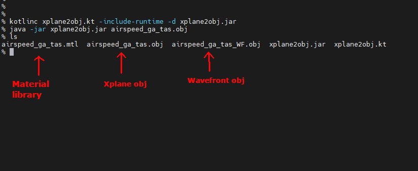
I originally wrote the code in python, but then switched to kotlin. If you prefer python, you can easily convert kotlin code to python using online utilities such as this. Here is my kotlin code for converting Xplane’s obj to wavefront obj, or here. Copy and paste this code into a local file, compile it and run it with the obj filename as the first argument. The exact procedure is going to depend on your operating system, so I can’t provide specific instructions. On linux, this is how you would run it. First, save the code as xplane2obj.kt. Compile it with kotlinc xplane2obj.kt -include-runtime -d xplane2obj.jar. Then run the compiled code using java -jar xplane2obj.jar myfile.obj where myfile.obj is the filename of the Xplane object. It should run with no screen output. If there are any printed messages, chances are something went wrong. Upon completion, there will be two other files created in the same directory. The first is myfile_WF.obj. This is the wavefront object. The second is myfile.mtl. This file contains the reference to the texture file. It is assumed the texture file has the same name as the obj file, in a DDS or PNG format (i.e., myfile.DDS or myfile.PNG). If the name of the texture file is different, or its format is different, just edit the mtl file and insert the correct names.
Next, open up Blender and import the wavefront obj file. If the texture file is in the same directory, you should be rewarded with the 3D object exactly as in Xplane.
Shown here is the airspeed indicator from the Xplane’s default C-172 aircraft, loaded into Blender.
Understanding Datarefs and Commands
A dataref is an internal variable of Xplane. For example, sim/cockpit2/gauges/indicators/airspeed_kts_pilot is the variable for the indicated airspeed. A complete list of datarefs can be found in the Resources/plugins directory of Xplane. There is also a searchable website, but I have found that the information there is sometimes different from what is in my Xplane. In any case, there is very little documentation on what each variable does. You have to guess based on its name. You can also use a dataref monitoring plugin (DataRefTool is a good one) while running Xplane, and see what values are contained in each dataref and then make an educated guess from there. Some variables are writeable, meaning you can use it to send information to Xplane. Some are read-only. Even the writeable ones don’t always stick. They may get overwritten by Xplane.
Commands are supposedly different than datarefs. They are meant to perform an action in Xplane. For example, sim/engines/throttle_up will increase the throttle up a bit. But you can also write a value to the dataref sim/cockpit2/engine/actuators/throttle_ratio[0] to do the same thing. The difference between writeable datarefs and commands is still unclear to me. The recommendation seems to be to use a command whenever possible instead of writing to a dataref. The complete list of commands can be found in Resources\plugins directory, but also on a searchable website (again, I have seen differences between what’s on that website and my Xplane).
Animating an object
Once the object is in Blender, animation is easy. For example, if you want to make the airspeed needle move, you need to allow it to rotate based on a dataref value. Here is how to do it:
First, you need to separate the airspeed indicator into two different mesh structures – the body and the pointer. Then, place the origin of the pointer at the pivot point of the required rotation (you need to look up how to do that). On the animation tab, select an animation keyframe number (we typically select 1 for the first keyframe, but it really doesn’t matter which number you select). Rotate the needle and place it where it should point when the airspeed is zero. Then save this keyframe position.
Find the Object Properties tab, and expand the Xplane properties. Click on Add Dataref. Then put in the dataref for airspeed. In this case, it is sim/cockpit2/gauges/indicators/airspeed_kts_pilot. Next we need to select the type of animation. There are three types of animations: Transformation (which is a movement), Show (which makes the object appear) and Hide (which makes the object disappear). Here we want Transformation because rotation is a transformation. Making sure the keyframe is in the first position, type in 0.0 in the Value box. Then click on the Add Dataref Keyframe button (just hitting return is not enough). The color of the value box should change as soon as it is accepted. Now we have assigned 0.0 knots to the first keyframe. Then add a second keyframe, rotate the needle to a different airspeed value, and type in the appropriate airspeed for that keyframe. Two keyframes should be sufficient for objects that behave linearly. For nonlinear motions, or for a more accurate representation, more keyframes are better.
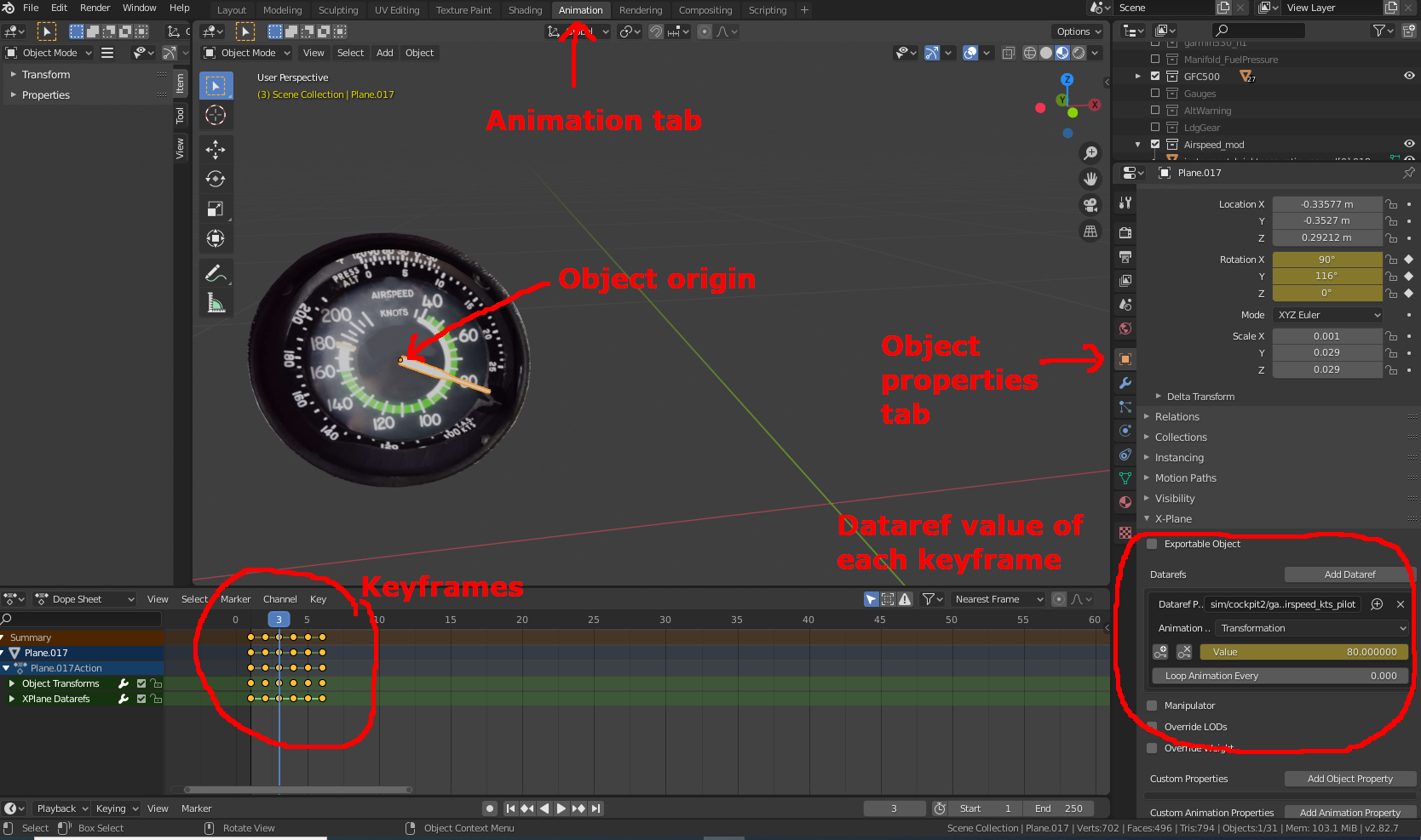
That’s pretty much it. We now have animated the airspeed indicator. When this object is exported, the obj file will contain the appropriate ANIM attributes to correctly display the airspeed.
Exportable Collections
Ideally, we should have a single .blend file for the entire airplane. This way everything can be lined up and visualized prior to exporting it to Xplane. To keep each object distinct, they should be placed in a different collection. A collection is a concept unique to Blender. Think of it as a folder within the blender file. Each collection will produce a separate obj file when exported.
Not all objects need to be exported. Some might be there just for your own reference when designing in Blender. There is an option in the Scene Properties tab to specify which collections should be exported. So check the boxes next to all the objects you want exported. Regardless of what you specify here, only the visible collections will be exported. That means you can always hide a collection (by clicking on the “eye” icon next to the collection) and that collection won’t be exported.
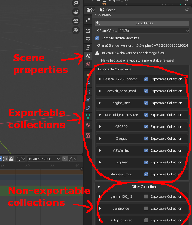
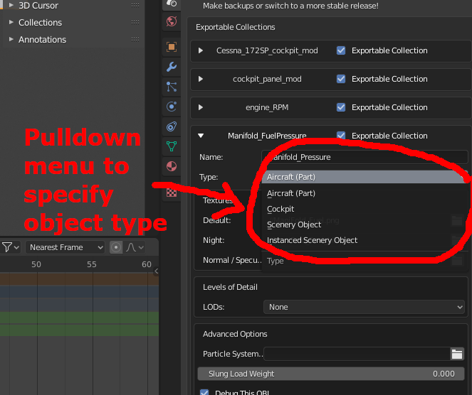
Under the Exportable Collection box, there is a separate pull-down menu to specify if this object is an Aircraft Part, Cockpit Object or Scenery Object. An airplane can have many Aircraft Parts, but can have only one Cockpit Object. Obviously, Scenery is not relevant for our discussion. Manipulators (clickable objects) can only exist in a Cockpit Object. Assigning a manipulator to an Aircraft Part will produce an error during export from Blender. Additionally, even though Blender will allow you to tag multiple objects as Cockpit Objects, only one will be eventually designated as Cockpit Object in Plane Maker. This is a potential area of confusion. I’ll say more about this later.
Replacing textures or redesigning an object
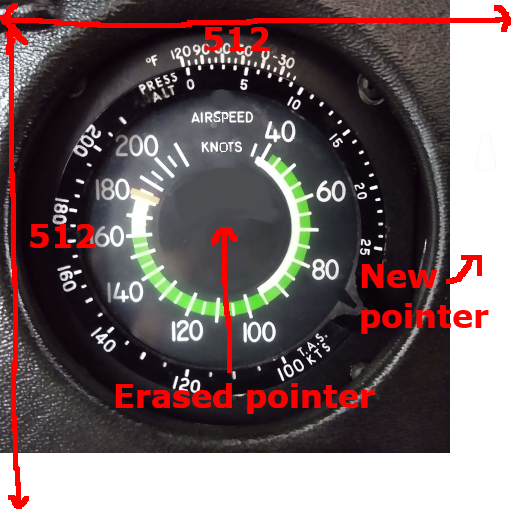
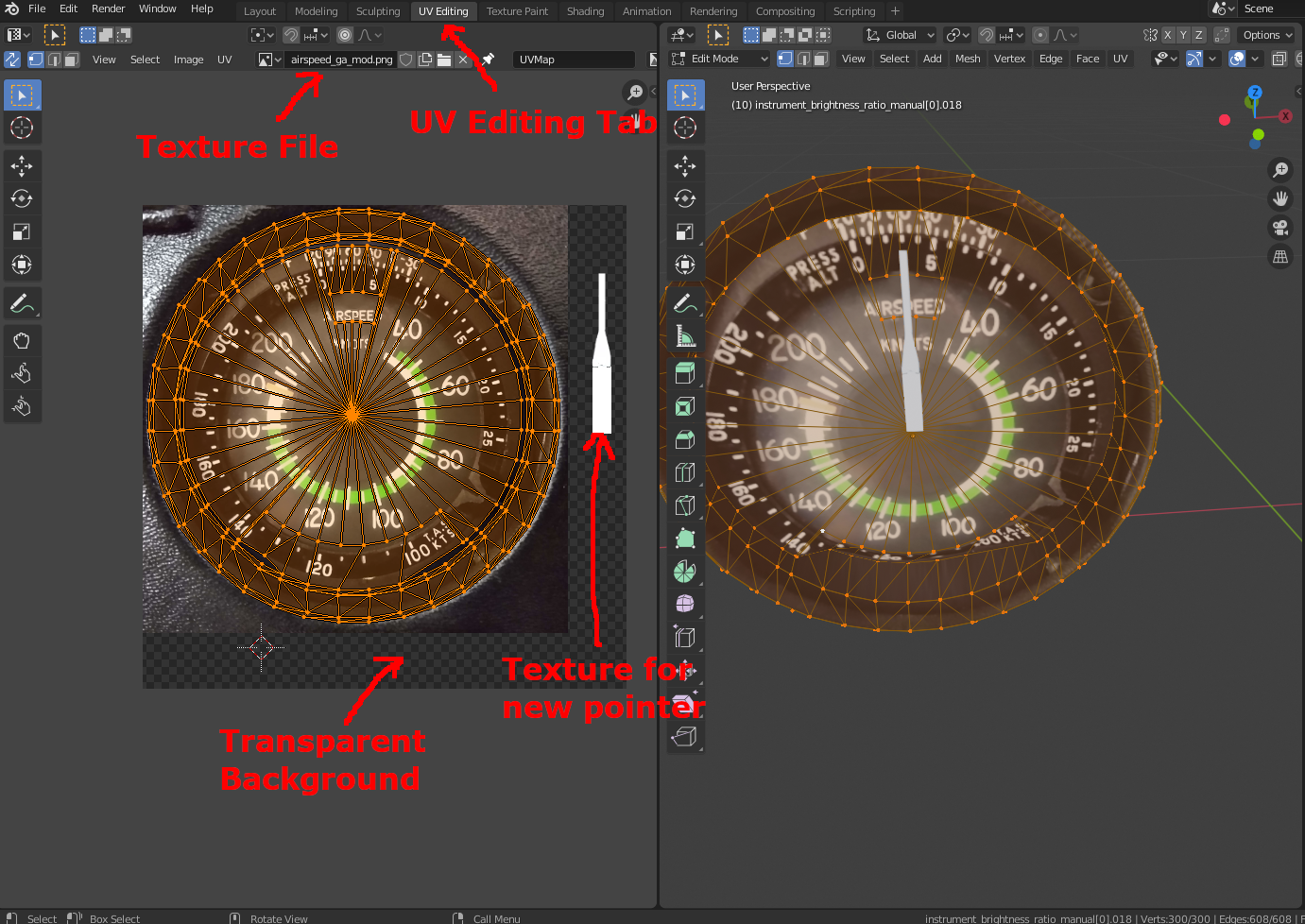
After importing the airspeed indicator into Blender, you may want to replace its texture image, or scrap the whole object and redesign it from scratch. In either case, take an actual photograph of your airspeed indicator, and UV wrap that onto the object. This is where having experience in Blender comes in helpful. I am not going to describe how to do all that. It is standard fare in Blender.
The image files should be in PNG or DDS form. Supposedly, DDS format renders faster. Both formats work with Xplane, and both can be edited with Gimp. The width and height of the image must be scaled to a power of 2, such as 512 x 512, or 512 x 1024 etc.. Of course, smaller images are better for speed. A lot of work is needed at this stage. With the airspeed indicator, the pointer needs to be inconspicuously erased. We can place the erased portion in a separate location to texture the new pointer, or simply create a white rectangle as the new texture. It depends on how fancy you want to get.
Also worth mentioning is that each object does not need to have a separate texture file. The same texture file can be shared across different objects. For example, the body of the airspeed indicator and the pointer (which are different objects within the same collection) can share the same texture file. It is common practice to assemble multiple images together, like a collage, into a single texture file.
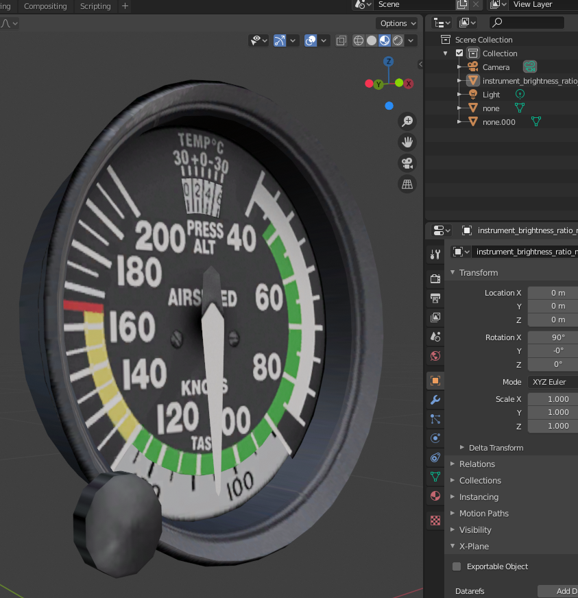
As mentioned earlier, Xplane uses three separate texture files. These should be put in the Scene Properties tab (this item is under the same place where you check the Exportable Collection box). This value has no impact on how Blender displays the objects. This is strictly for inserting the appropriate file names when Blender exports these objects.
Manipulators and the Cockpit Object
Manipulators are objects in the cockpit that you click, drag or rotate with a mouse. Examples are throttle control, yoke, switches, etc… If you have joystick controls for all functions and don’t intend on using a mouse at all, then these manipulators may not be necessary. However, even with an external yoke/rudder/throttle quadrant, we may still need to push buttons to program the GPS, or autopilot etc..
Since all of the manipulators were lost in the Xplane-to-wavefront conversion, we need to recreate them. The default Cessna 172 has hundreds of manipulators, and recreating them in Blender would take a lot of time. But as a pilot, I don’t really care if the simulator has every little switch and control knob. Light switches, door knobs and even master switches are not necessary for my purpose. This eliminates nearly 80% of the manipulators from the default Cessna 172.
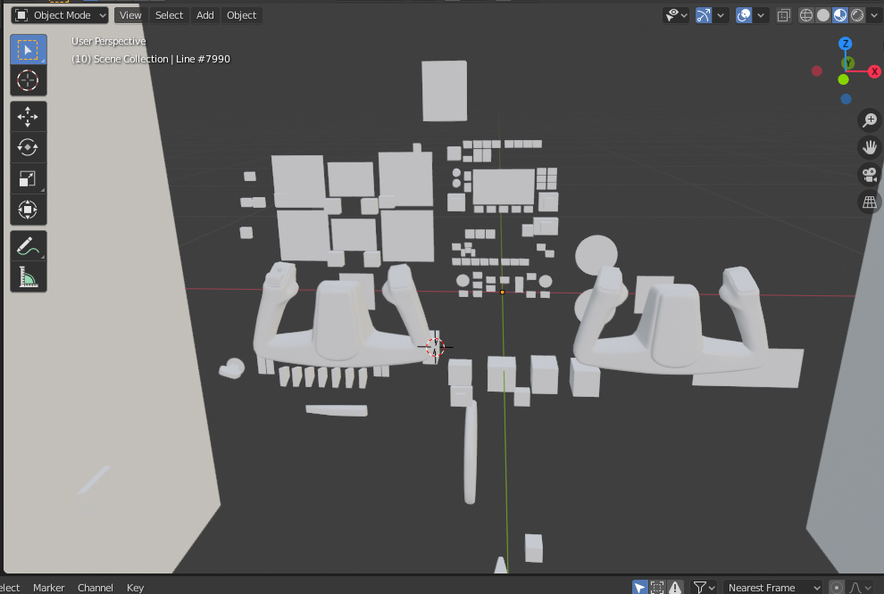
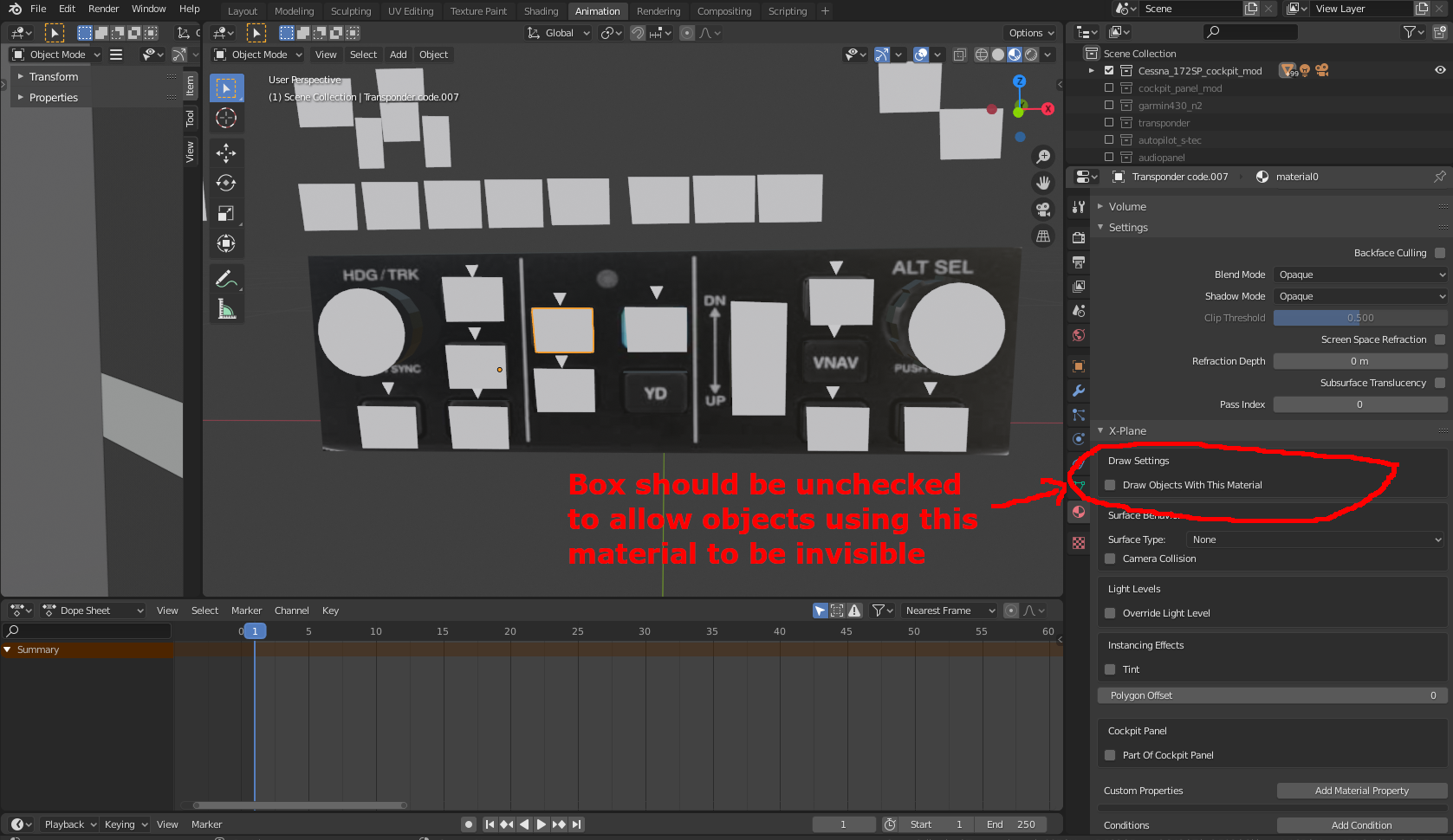
A manipulator is assigned in Blender the same way as an animated dataref. As stated earlier, only the Cockpit Object is allowed to have manipulators, and there can be only one Cockpit Object. As a result, all of the manipulators are combined into a single object. On the default Cessna 172, this file is Cessna_172SP_cockpit.obj, which can be found in the root directory of the aircraft folder. Every push button, lever, knob etc.. has an associated clickable object in this file. They are rendered with an invisible material, so they won’t appear on Xplane.
If you open the file Cessna_172SP_cockpit.obj with a text editor you will see that it has no associated texture file. That’s because nearly everything in it is a hidden object. (Actually, there can be a few visible objects in this file, which will be wrapped with an internal texture file cockpit_3d\-PANELS-\panel.png. I’ll discuss this in detail later). If you convert this obj file to Blender, it will show a 3D cockpit layout, but it will look a bit weird. Most objects here have simple shapes – circles, rectangles, cubes etc.. all gray in color. Every object here exists only for the purpose of capturing the mouse clicks. The Blender view of this file is shown in the figure above.
Let’s consider the throttle lever. If you display it along with the actual throttle lever (which is part of the cockpit_panel.obj), it will look like shown below.
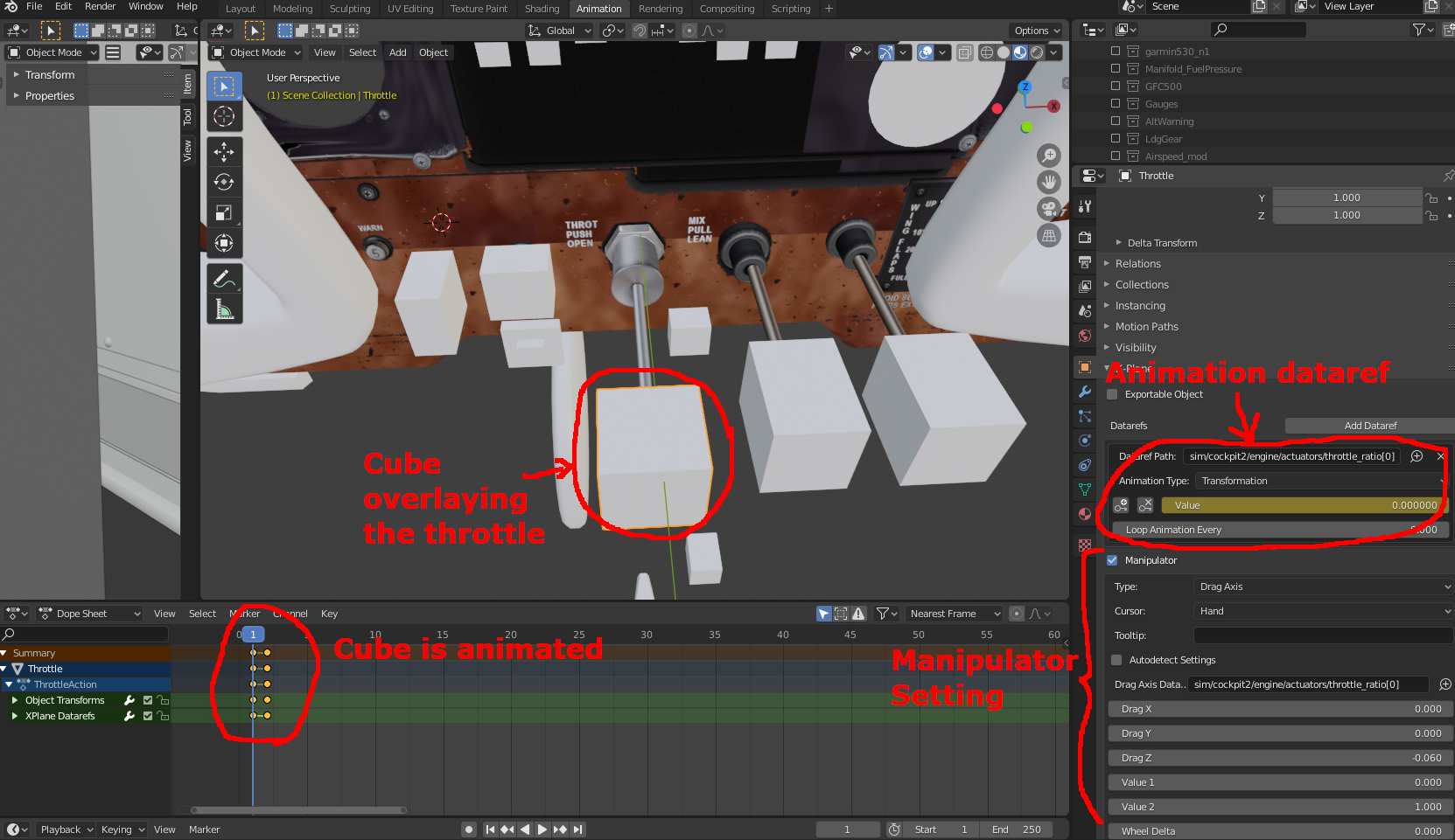
In this example, the grey cube overlaying the throttle lever is the clickable object for the throttle. It is set as a Drag Axis (push-pull) manipulator. The Hand setting tells it to display a hand icon (in Xplane) when the cursor is over it. The dataref for this manipulator is sim/cockpit2/engine/actuators/throttle_ratio[0], which is a writeable dataref. The other values in the manipulator setting specify the range of values to assign to this dataref when the throttle is moved. The clickable object has to be animated as well (using the same dataref), because it needs to move as the throttle is pushed in. The actual throttle should also have the same animation using the same dataref, so both the clickable object and the real throttle always stay together.
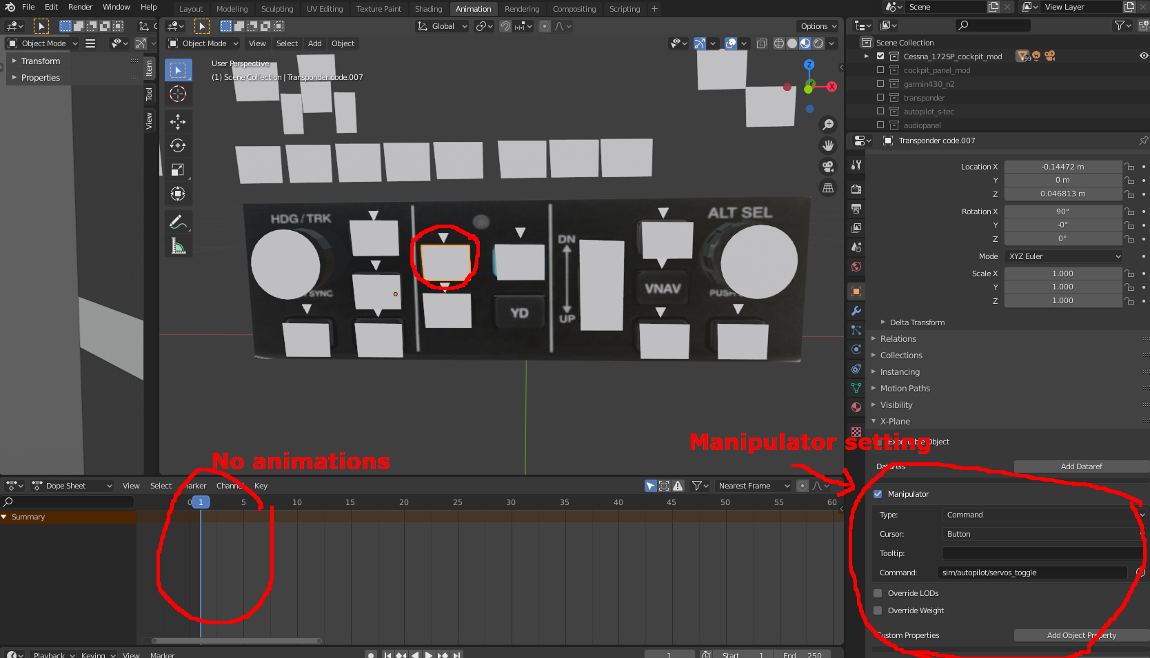
Not all clickable objects need to be animated. The clickable object for a push button, as shown on the autopilot below, is a simple rectangle sitting over the actual button. The button itself is animated (to show a pressed state), but the clickable object does not need to be animated because the button does not move very far when pushed.
All of the manipulation objects in the Cockpit Object collection should be drawn with a single material type that should be designated as invisible. This is done in the Materials Properties panel by unchecking the “Draw Objects with this Material” as shown below. If it is checked, then all these grey objects will show up in Xplane, making a very ugly panel.
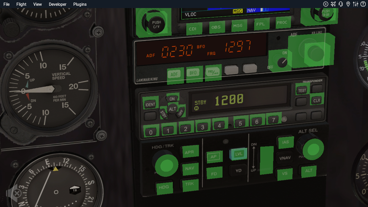
In Xplane, all of the clickable objects should show up in green if the View->Show Instrument Click Regions is enabled. This is shown below.
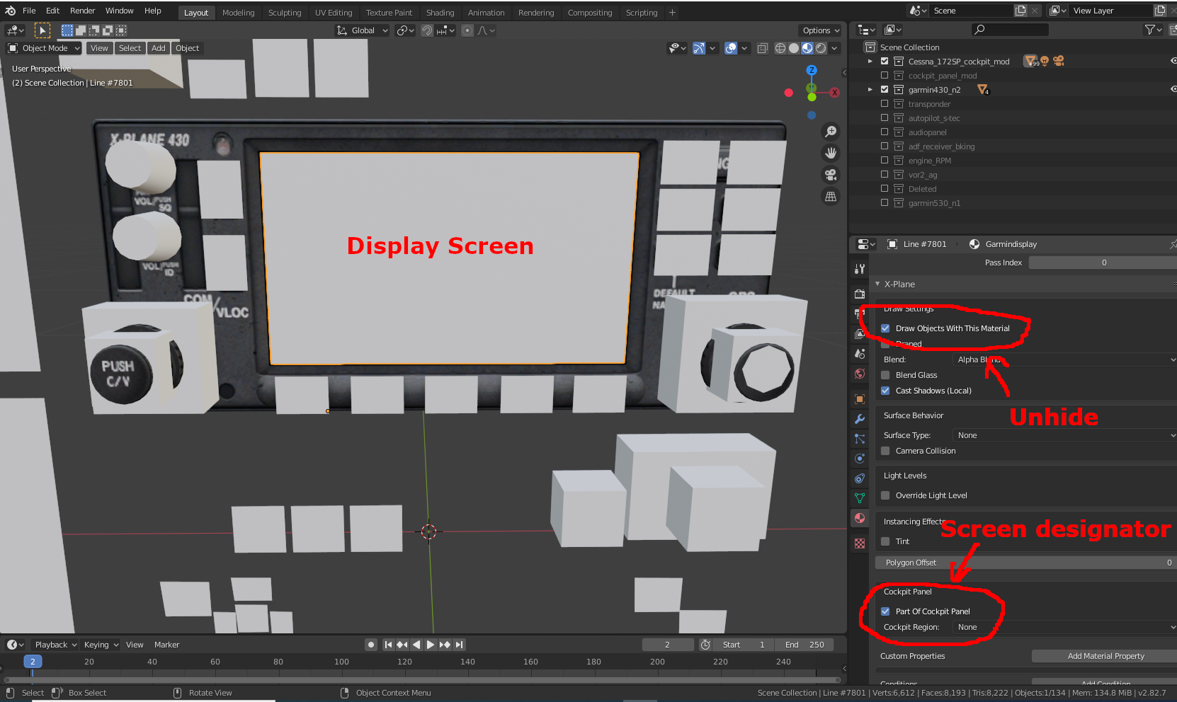
Cockpit Display Screens
Cockpit instruments that contain a screen, like the GNS430 or the G1000 are a different object type. Their screens should be drawn as rectangles in the same Cockpit Object collection, but using a different material that is not hidden. This material should also be designated as “Part of a Cockpit Panel”. These objects will ultimately get textured in Xplane by an image file located in cockpit_3d\-PANELS-\panel.png. We don’t need to specify this texture file in the export collection parameter list. Xplane will automatically do that.
When Xplane runs, it will draw the various screens to panel.png during every frame cycle. Actually, the panel.png file is just a template. It doesn’t actually get overwritten during every frame cycle. Instead, the file contents are held in memory and updated during every frame cycle to show the screens.
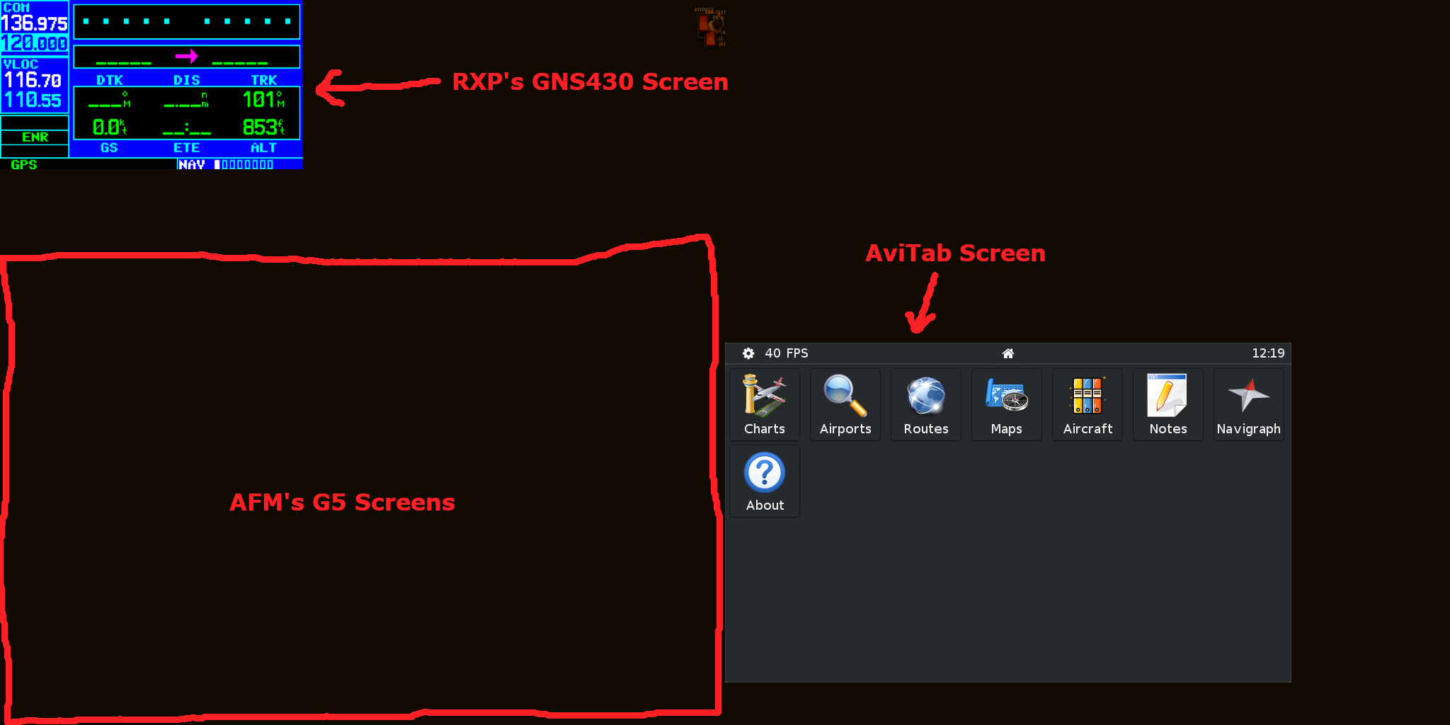
The code for producing the displays such as GNS430, GNS530, G1000, and a large number of other instrument displays are in the Xplane’s main engine. But a custom display can also be written with an external plugin. For example, in my cockpit, I have two G5 screens (purchased from AFM), GNS 430 (purchased from RealityXP), and Avitab for the iPAD tablet. I opted for RealityXP’s GNS430 because it more closely resembles the real thing than Xplane’s internal GNS430. The default Cessna 172’s panel.png size is 1024 x 1024. This was too small to fit all of the above screens. So I increased it to 2048 x 1024. All you have to do is to create a new blank panel.png file of the size you want. But like any other texture file, the size must conform to the power-of-2 rule.
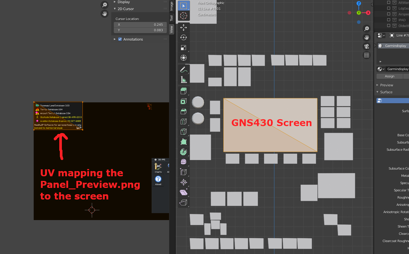
We can get the contents of the panel.png memory by executing the command sim/operation/make_panel_previews (using the DataRefTool plugin). This will write the image to a file named Panel_Preview.png in the cockpit_3d\-PANELS-\ directory. Every cockpit screen should write to a different area of the image. Overlapping images will obviously screw up all the display screens. Avitab has an option to specify the pixel location of its image within the panel.png file. RealityXP also has an option to specify its image location. The snapshot image is shown below. For some reason, the G5 screens were not showing, but I had to do some trial and error and figured out it was actually being written to the lower left corner.
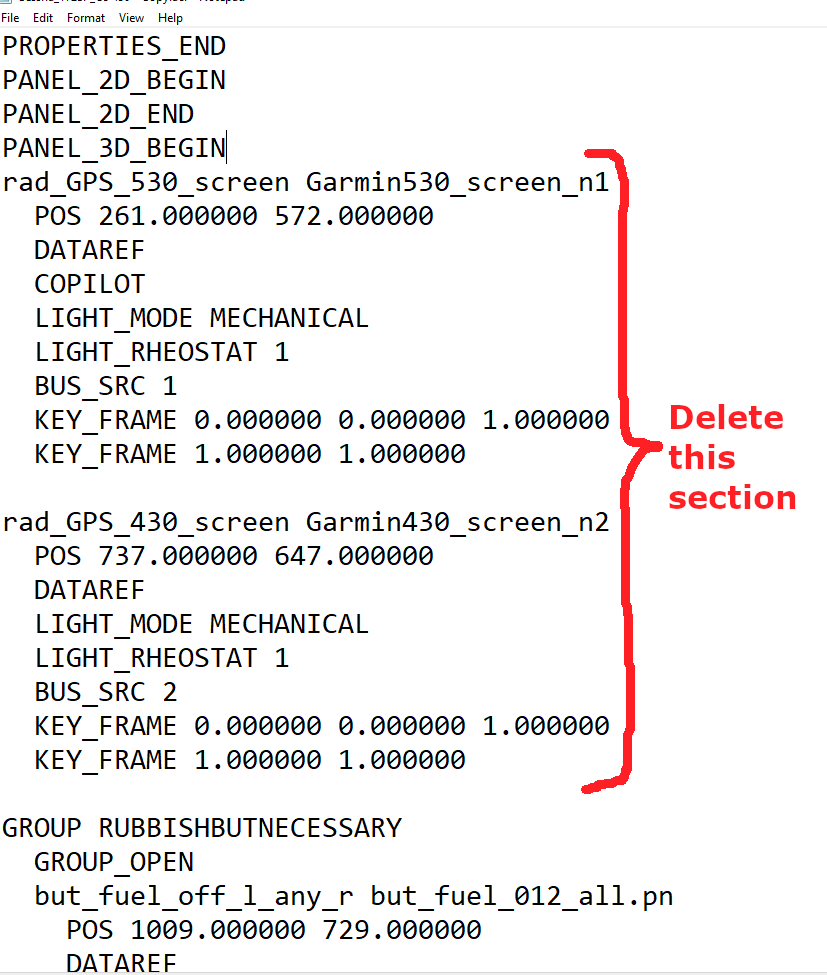
In the C172’s acf file, we also need to disable Xplane’s own GNS430 screen as well as the GNS530 screen. Even though I had deleted the GNS530 object from the Cessna 172’s avionics stack, Xplane will continue to write its screen output in panel.png. This is obviously unnecessary and will only slow down Xplane. This can be easily removed from the acf file with a text editor. In fact there is another group of objects labelled RUBBISHBUTNECESSARY, which as far as I could tell, is a bunch of annunciators that serve no purpose, so I removed all of them as well.
The Panel_Preview.png file can be used to UV map the displays to the correct areas of the file (panel.png file cannot be used because it is a blank file). Even though we are using Panel_Preview.png, Xplane will actually use its internal panel.png to texture the object during runtime.
Using Planemaker to add screens to panel.png
Planemaker has built-in instruments that can be placed on the panel.png texture, and then UV mapped to an object. This menu is under Standard-> Panel: 3D. There are a large number of these instruments, ranging from simple light indicators to EFIS panels. Below is an example of placing an EFIS on to panel.png in Planemaker.


In the above example, we could map the image of the EFIS to a cockpit panel.
Designing the GFC-500 Autopilot
In this section, I will describe the steps for designing the GFC-500 autopilot. This autopilot does not come with Xplane, so it is a useful learning exercise.
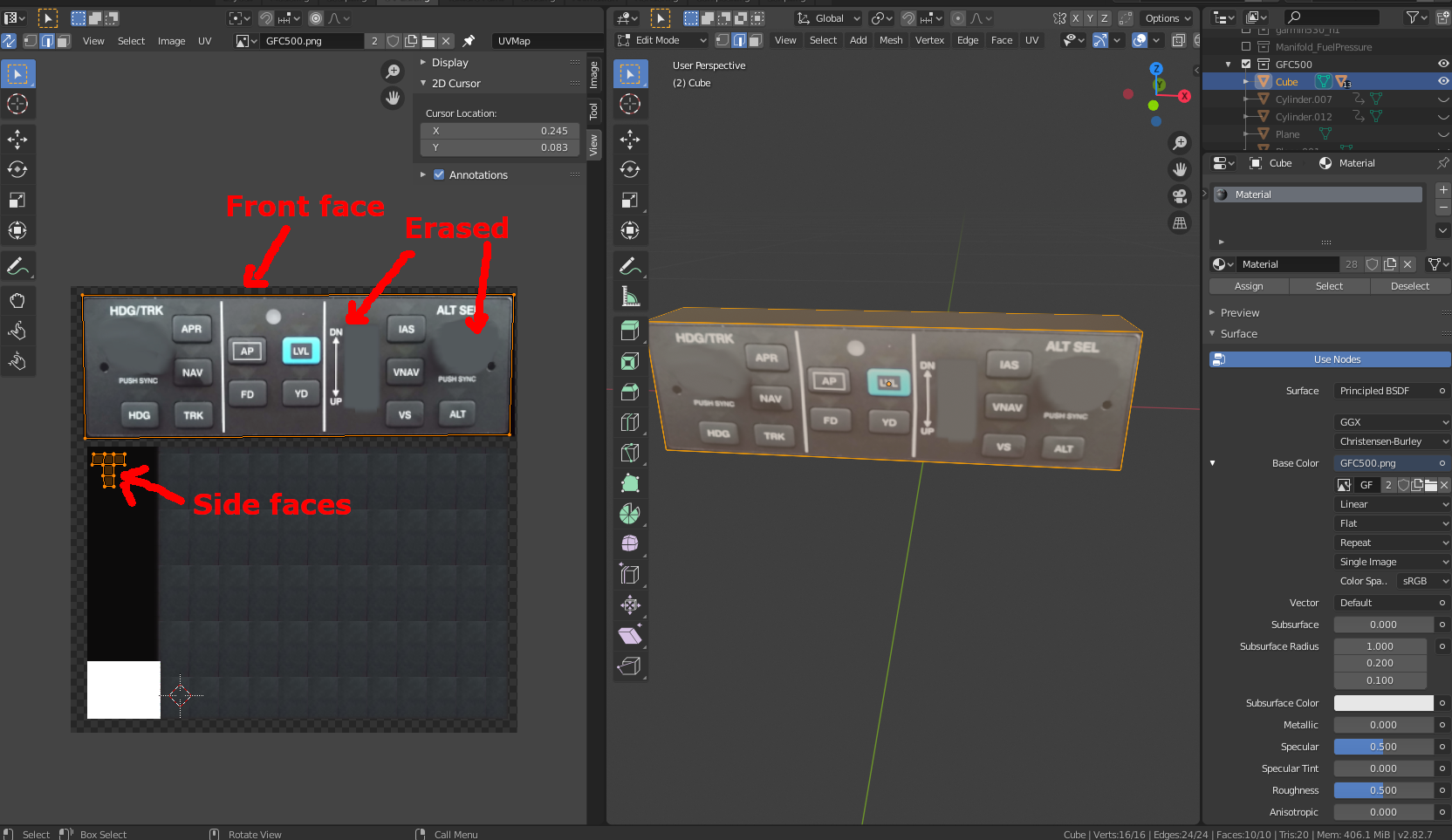
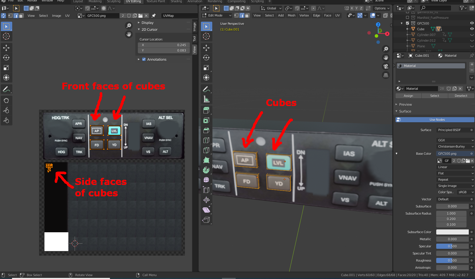
Using the cockpit panel in Blender as the backdrop (which is cockpit_panel.obj), use a primitive cube to create a box of the correct size and and place it in the desired location in the avionics stack. Place this cube in a new collection called GFC500. One could also create the bezel around the front face to give it a more realistic look, but I didn’t. The best time to make such modifications on the cube is now, before UV unwrapping it. Its hard to make structural changes later.

The next step is to take an actual photograph of the unit and use it to UV wrap onto this cube. A texture is needed for the side faces as well, which can be a simple patch of black on the image. At this point, all the buttons and knobs are just images, not actual objects.
Then create a few primitive cubes and place them over the buttons, making them project slightly outwards like a real push button. Make sure these cubes are all in the same GFC500 collection.
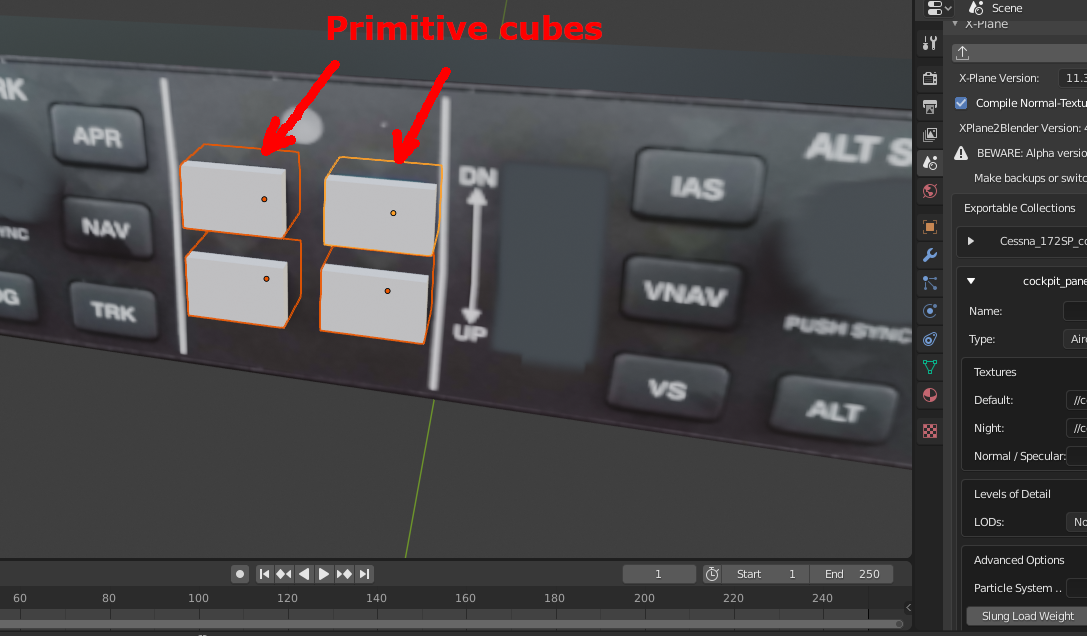
The next step is to apply textures to the small cubes. The same texture file as the body can be used for this. Repeat this for all of the buttons on the panel.
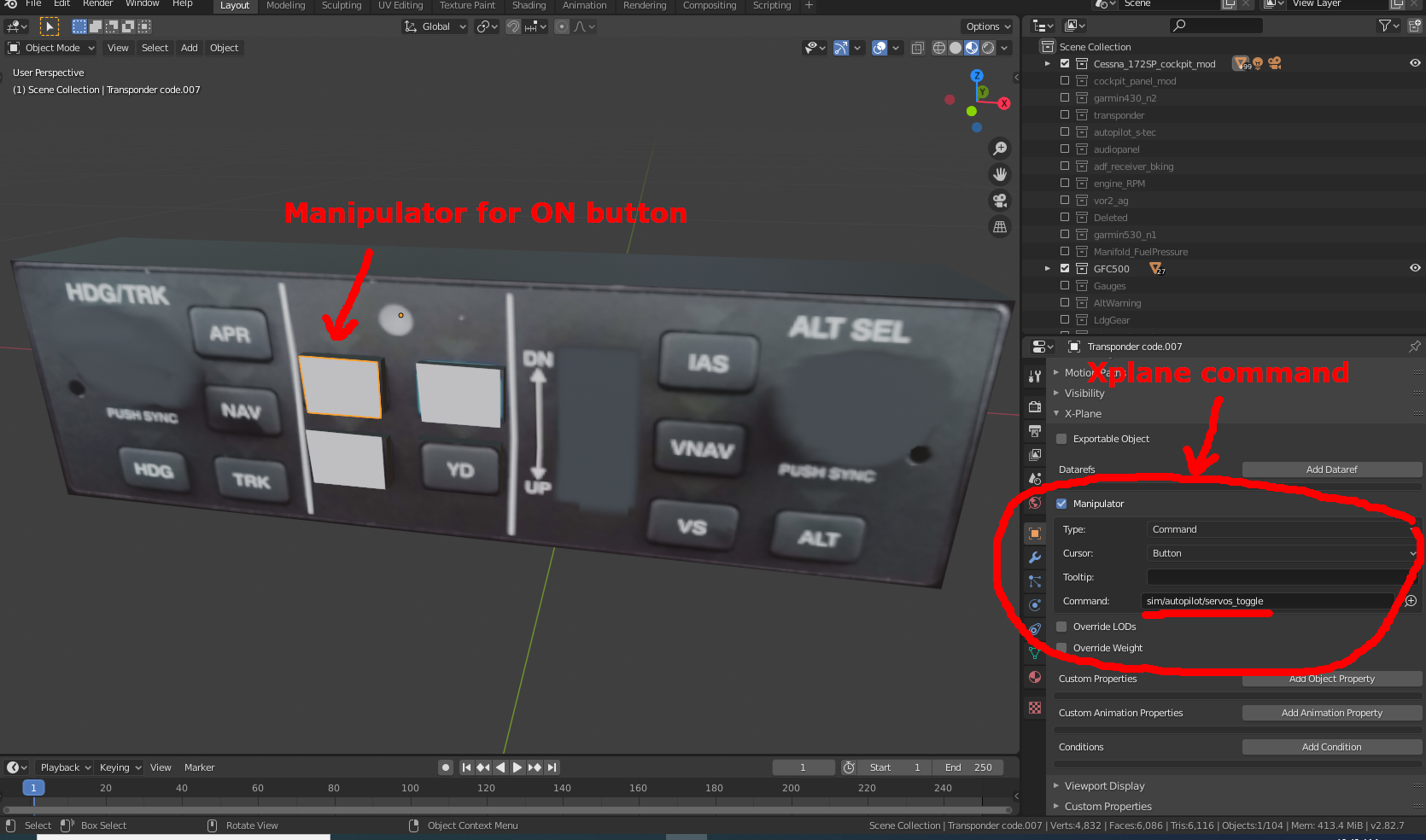
The next step is to create a clickable object for each button to serve as manipulators. You can simply duplicate the cubes, or draw clickable rectangles on the faces of the buttons. Make sure to move these clickable objects to the Cockpit Object collection. These clickable objects should be assigned the same invisible material as the other manipulators.

Next we need to assign commands to the clickable objects. For example, the ON button on the autopilot should engage the servo motors. The command for this function is sim/autopilot/servos_toggle.
Next, the button (not the clickable object) should be animated to show the pushing action. Hide the cockpit object collection out of the work space, and create two keyframes for the button. The first keyframe will be the normal state (sticking out a bit), and the second keyframe should be in the pushed state (flat with the panel face).
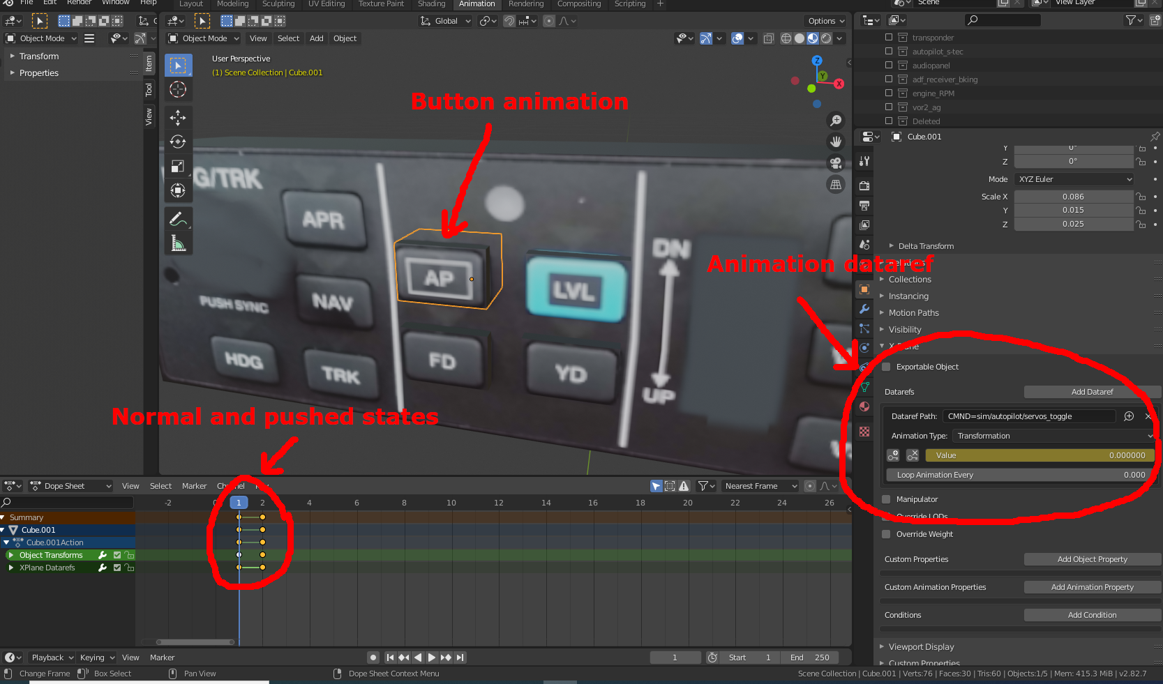
Then a dataref has to be attached to this manipulator. We could use the dataref sim/cockpit2/autopilot/servos_on but we can also do it differently. We can use a temporary dataref derived from the command. This can be done with CMND=sim/autopilot/servos_toggle. This dataref will produce a value of 1 when the command is being invoked (button pushed) and 0 when the button is not being pushed.
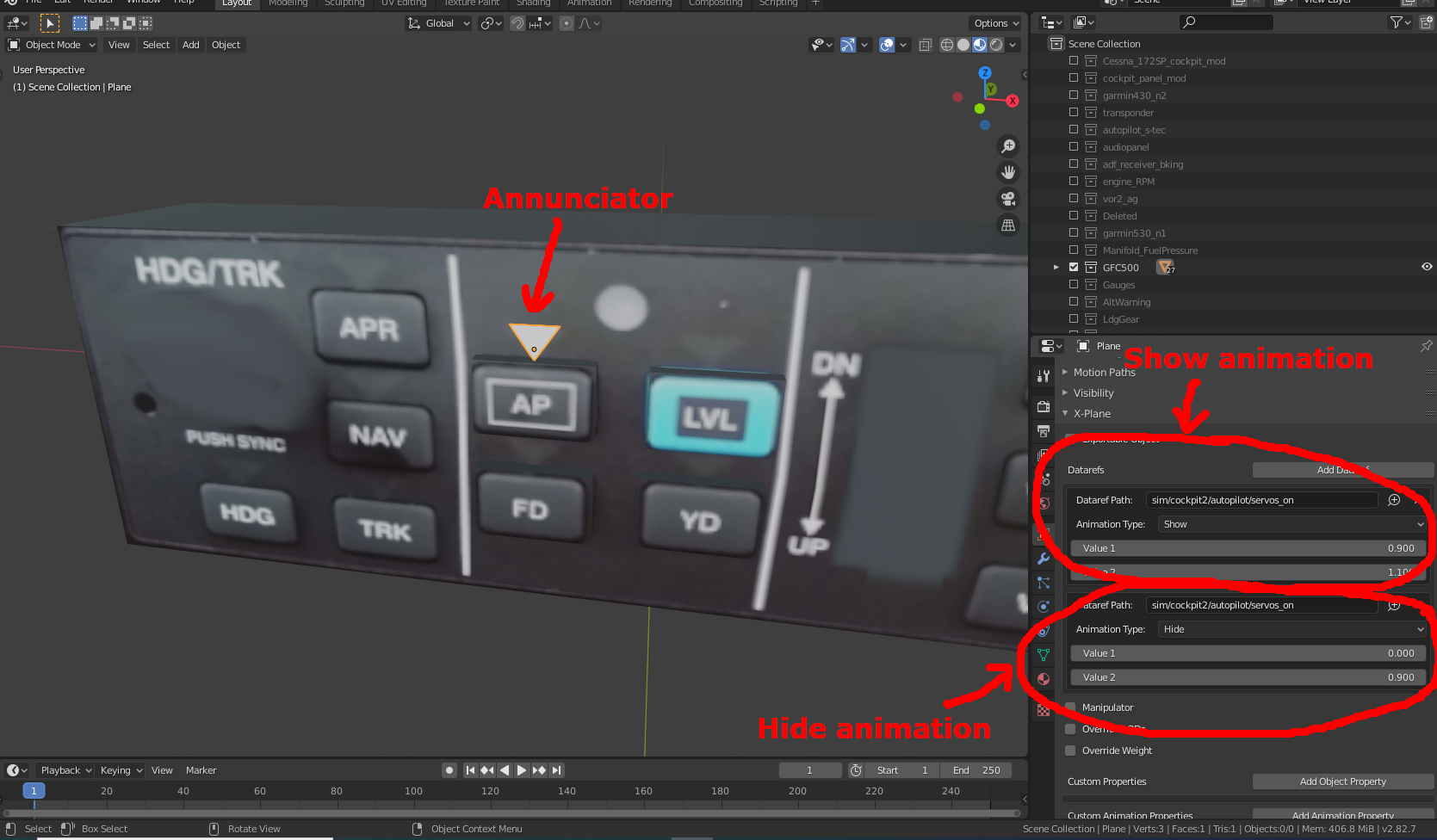
The above steps should be adequate to make the push button work, but we should also create the annunciator corresponding to that button. On the GFC500, a white triangle pointer lights up when a button is pushed, and it extinguishes when the button is pressed again.
Draw a simple triangle above the button, and use the same texture file used for the autopilot with a small white patch to color it.
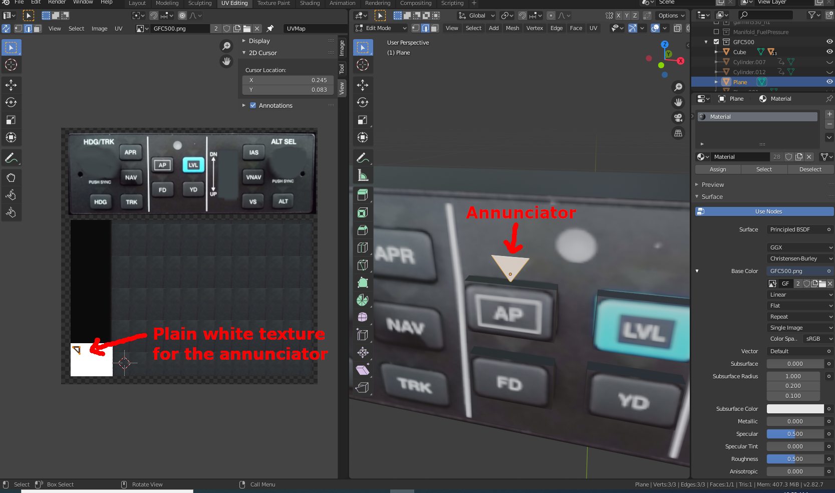
This triangle has to be animated, but it does not need keyframes because it does not move. It simply appears and disappears. This can be done in the Object Properties tab – the same place where we assign dataref values for animated objects – except this time choose Show as the animation type. Then select sim/cockpit2/autopilot/servos_on as the dataref and assign the conditions when it should be shown and when it should be hidden. Some of these values are not clearly documented, so you would have to run DataRefTool inside Xplane to find out.
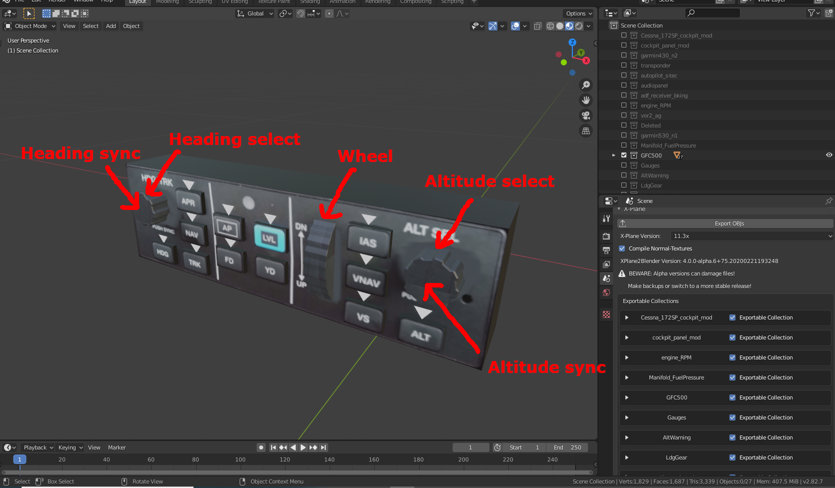
We have to repeat this for all buttons on the panel. We also have two rotating knobs for changing altitude and headings, push buttons to synchronize the current altitude and heading, and a wheel for changing vertical speed. All of these need appropriate manipulators, animations, and keyframes.
I also chose to add a tiny LED screen on the GFC500 to show the requested vertical speed. This display does not exist on the real GFC500. In Planemaker (under Panel: 3D), I placed an object named EFIS_disp_VVI.png in an unused parts of the panel.png. In Xplane, I took a snapshot of Panel_Preview.png. Then in Blender, I created a tiny display screen on the face of the GFC500 (in the cockpit objects collection) and used the Panel_Preview.png to UV wrap this screen.


You can download my fully completed GFC500 autopilot object file for Xplane here, and the blend file.
Exporting objects from Blender
Click on File->Export->Xplane (obj). The file name is not relevant. Blender will export all visible exportable collections using the names of the respective collections. Alternate names can be specified for each collection in the Exportable Collections panel. If there are any errors, it will be in an internal log file named xplane2blender.log. Blender uses internal files (i.e these are not written to disk). You can access this with the Blender’s text editor.
Next, copy the obj files and their texture files into the Xplane aircraft directory. You could create a separate directory named objects/custom to keep your objects separate. Then fire up Plane Maker.
Importing objects into Plane Maker
Make a copy of the acf file you are modifying, and open that file. Under Standard->Author, write the appropriate description of this airplane so that it is recognizable in Xplane.
Next, go into Standard->Misc Objects. This is where all the 3D objects are assembled. If the object was placed in the desired location in Blender, there is no need to adjust the X,Y,Z position or rotations here. They could all be set to zero, and the objects should be in their correct positions.
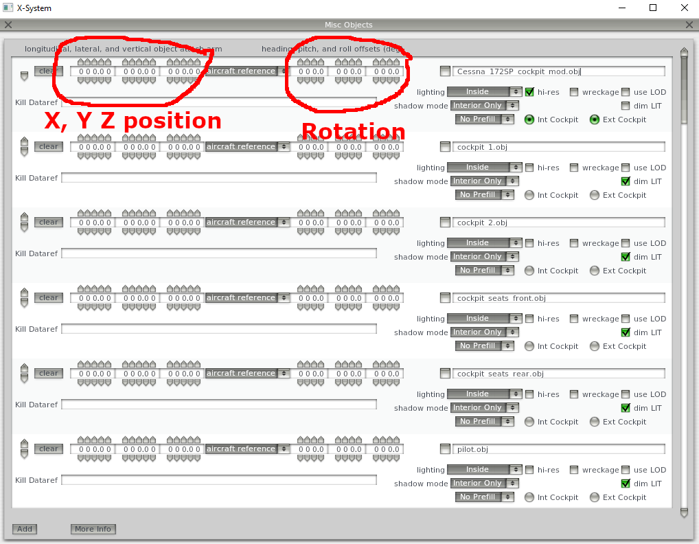
The Int Cockpit is the radio button that indicates it is a Cockpit Object (the one that contains manipulators). Hi-res should be checked for instruments that require higher resolution rendering. The Inside/Outside/Glass Inside/Glass Outside control how these items are displayed, and there is a pop-up help available for these options.
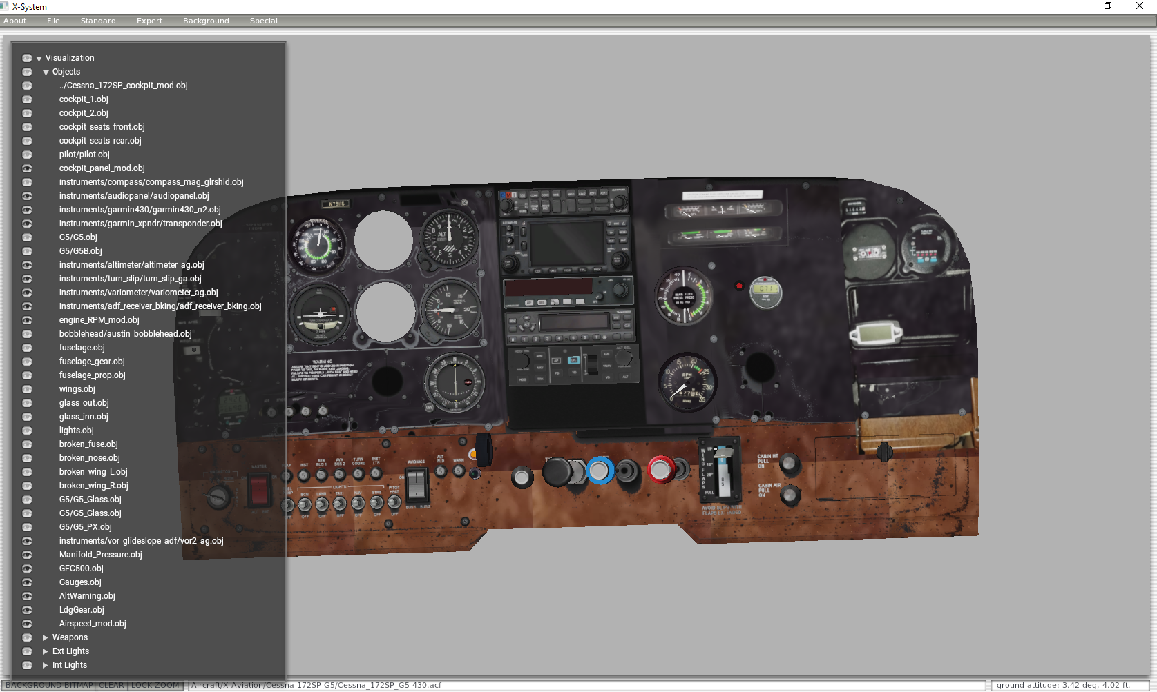
Once all the objects are added to the list, go to the front page of Plane Maker, hide all the items except the ones related to the panel. Zoom in close using the “=” key. It should look something like the figure below. If it does, then the next step is to open it in Xplane.
Check it out in Xplane
The last step is to open the airplane in Xplane and check for the expected look and functionality.
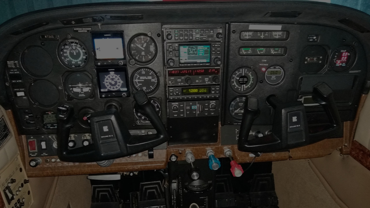
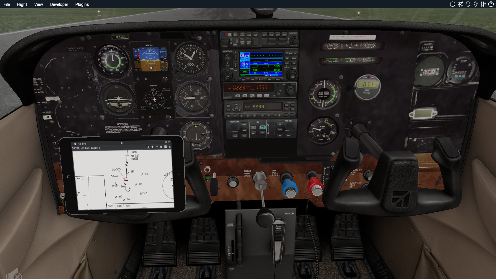
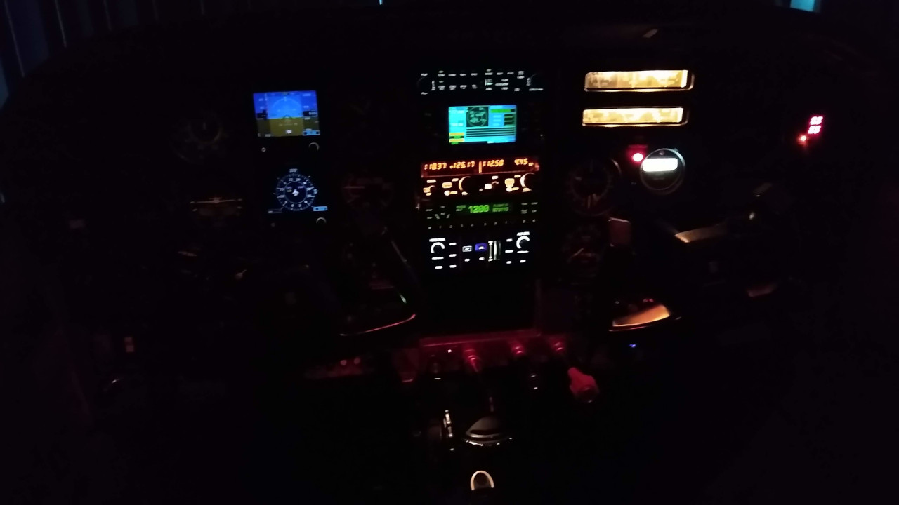
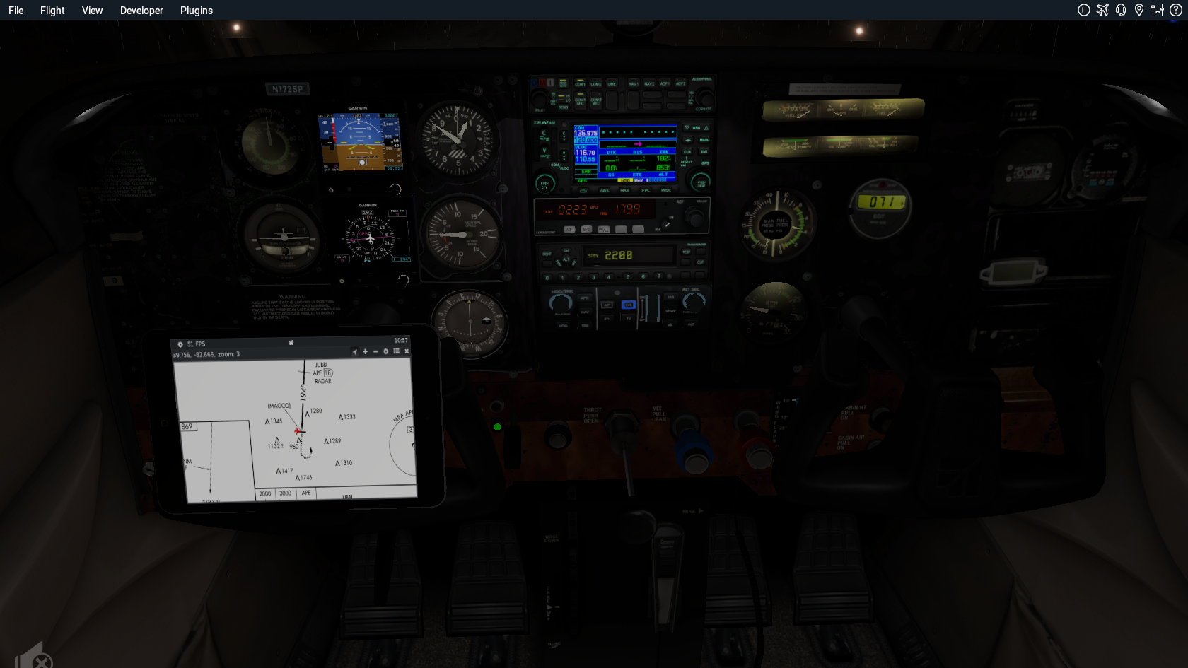
The image below shows a new airplane I created to mimic my club’s Cessna 182R, starting from Xplane’s default Cessna 172. In addition to the instruments, I had to add a landing gear switch, fuel pressure, manifold pressure, cylinder head temperature and a bunch of other things. I tried texturing the panel based on an actual photo. The propeller and engine specifications were changed to match the 182. Overall, it flies nearly identical to the real 182, and it will serve as a great training tool for maintaining proficiency.
Lighted Textures and Normal Textures
Objects are displayed using the default texture whenever there is ambient light. As the ambient light declines (at dusk or at night), the default texture slowly disappears and is replaced by the lighted texture. The lighted texture is basically the portions that should glow in the dark.
A lighted texture can be created by modifying the default texture in gimp. It is important to start from the same texture file because the same UV co-ordinates are used for both textures, so every pixel’s position should remain at the same location. There is also a nifty light filter tool in gimp that can be used to create the illusion of a light bulb. The layering concept in gimp is a great way to cut different parts of the image and modify them separately.
While the default texture is allowed to have an alpha channel (transparency setting), the lighted texture should be opaque. In other words, all non-emissive areas should be drawn in black. This can be easily created in gimp by creating a layer with a black fill, and then laying the portions that should be emissive on top of it.
Normal maps allow surfaces to be rendered with fine structural details without adding extra vertices. These can be created in Blender by first creating a high-resolution object with lots of features, and then mapping those features to a low-resolution object using a process known as baking. Among other things, baking can be used to create a normal texture file. When applied to a low resolution object this will make it look similar to the high-resolution object.
Leave a Reply