The commonly taught explanation for why we need to lean the mixture as we climb is not quite correct. Carburetors are supposedly volumetric (i.e. they’re supposed to deliver a constant air:fuel ratio by volume). The density of liquid fuel does not change with altitude, but the density of air does change. As a result, the mixture will become richer as the air density decreases. To maintain a constant fuel-air ratio, we need to reduce the fuel flow. This is how nearly every pilot is taught. But that explanation is not quite correct. Carburetors do not maintain a constant volumetric ratio of fuel and air. The fuel flow actually declines as air density declines, except that it does not decline proportionally with air density; and this is what makes the mixture become richer as we climb. The mixture also becomes richer when we reduce throttle, which is a similar effect. We can examine all of these by going back to the basics.
Mathematics
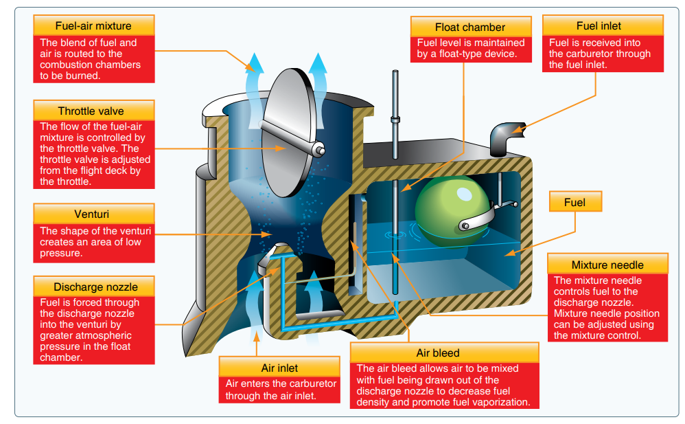
As air flows through the carburetor’s constriction, the pressure will drop. This can be written as:
\delta P = \frac{1}{2}\rho_a {v_a}^2 \hspace{2cm}(1)where \delta P is the pressure difference (compared to ambient), \rho_a is the density of air, and v_a is the air velocity in the constriction. This pressure difference \delta P is what forces the fuel from the bowl into the venturi.
Next, we need to relate \delta P to the fuel draw rate. For this, we need to use the orifice plate equation, which states
Q_f = K\sqrt{2\delta P \rho_f}\hspace{2cm}(2)where Q_f is the gravimetric fuel flow rate, \rho_f is the fuel density and K represents the geometry of the orifice. Larger hole will have a larger value of K.
Combining the above two equations, we can get
Q_f = K\sqrt{\rho_a \rho_f}v_a.\hspace{2cm}(3)The velocity of air v_a is a function of engine rpm, engine displacement and the carburetor’s diameter. We can write this velocity as:
v_a = \frac{V f}{2D}\hspace{2cm}(4)where f is the engine rpm, V is the engine displacement volume, and D is the carburetor’s diameter. As a result, we can get the gravimetric fuel flow rate as:
Q_f = \frac{KV f}{2D}\sqrt{\rho_a \rho_f}.\hspace{2cm}(5)The mass flow rate of air depends on the density and the displacement rate of the engine. This can be written as:
Q_a= \rho_a v_a =\frac{V f\rho_a}{2D}.\hspace{2cm}(6)Finally, we can divide Q_f by Q_a to get the ratio of the gravimetric fuel flow rate and the gravimetric air flow rate:
\frac{Q_f}{Q_a}= K \sqrt{\frac{\rho_f}{\rho_a}}.\hspace{2cm}(7)This is the key result. The fuel-air mixture is linearly dependent on the mixture setting (K). If this was all, then the original statement that the carburetor maintains a constant air:fuel ratio by volume would be correct. However, the second term in the above expression is the density ratio \sqrt{\frac{\rho_f}{\rho_a}}. This means that the fuel-air mixture does decrease as the density of air decreases. But it doesn’t decrease proportionally. If the second term were {\frac{\rho_f}{\rho_a}} (without the square root), then we would never have to adjust the mixture at all. It could be set at the factory by fixing K. The square root makes the fuel-air mixture change slowly rather than proportionally. As the density of air decreases, the fuel-air mixture will become richer (but not by the same proportion as the density change). So we do need to adjust K to maintain the same fuel-air mixture.
In the above description, we are implicitly assuming that the fuel density remains more or less constant. Strictly speaking, the fuel density does change slightly with temperature, so we would need to adjust mixture when the fuel temperature changes as well (which is not the same as the air temperature change).
Example 1
Consider an aircraft climbing from sea level to 8000 ft with full open-throttle. The air density at 8000 ft is about 25% smaller than at sea level. Not accounting for temperature changes, the manifold pressure will drop by approximately 25%. From equation (7), assuming you leave the mixture setting unchanged (K remaining unchanged), we can see that the mixture will become richer by 15% (not 25%). This comes from \sqrt{\frac{1}{0.75}}. We can restore the mixture by making the orifice smaller (which would make K smaller). This is exactly what the mixture knob does.
Notice that if the carburator had maintained a constant volumetric ratio of air to fuel, the mixture would become richer by 25%, not 15%.
Example 2
Next, lets look at a change in throttle setting at the same altitude. An ideal example of this is taxiing vs takeoff. Looking at equation (7), we might be tempted to conclude that throttle setting has no relationship to the mixture setting. But the important point to remember is that air density \rho_a is related to manifold pressure. \rho_a will be equal to ambient density only when the throttle is wide open. With the throttle at a low setting, the intake manifold pressure will be low, leading to a lower air density value \rho_a. For example, taxiiing at 10″ of manifold pressure is equivalent to flying with a wide open throttle at 28,000 ft. Following the same argument as before, this would lead to a richer mixture. For example, if the mixture is set to full rich, while taxiing at 10″ of manifold pressure, the mixture will be richer by 72% (which comes from \sqrt{\frac{29.92}{10}}).
Assumptions
In the above discussion, we have assumed a single value of air density \rho_a. In fact, \rho_a in equation (1) is actually the air density in the venturi, and the \rho_a in equation (6) is the air density in the intake manifold. These are not exactly the same. The air density in the venturi will be higher than in the manifold.
We are also assuming that our goal is to maintain a fixed air:fuel ratio. This is not always the case. The stoichiometric mass flow ratio for complete combustion is 1:14.7. That is, we need 14.7 grams of air for each gram of fuel. However, due to other factors such as cooling and combustion efficiency, the ideal mass flow ratio is not always 1:14.7. At very high power outputs, it is better to use something like 1:12 (which is known as rich of peak) and at low power settings it is more efficient to use something like 1:16 (known as lean of peak). As a result, even if there is no change in air density, the mixture should be adjusted whenever there is a change in power. On takeoff, the mixture should be slightly enriched. Once the power is reduced after take-off, the mixture can be leaned.
Leave a Reply